Category: Software
Static and extern keywords in C
These keywords used to literally haunt my dreams back in the day, when I was a freshman at BUT. I was just getting grips with C at that time and whenever I tried to use them, I got it all wrong. I’m talking about the magic keywords — static and extern. Both of them have multiple uses in C code and slightly different behavior in each case. For a beginner it might seem like a total anarchy, but it will start to make sense at some point. So, let’s get to the point …
Both of these modifiers have something to do with memory allocation and linking of your code. C standard[3] refers to them as storage-class specifiers. Using those allows you to specify when to allocate memory for your object and/or how to link it with the rest of the code. Let’s have look on what exactly is there to specify first.
Linking in C
There are three types of linkage — external, internal and none. Each declared object in your program (i.e. variable or function) has some kind of linkage — usually specified by the circumstances of the declaration. Linkage of an object says how is the object propagated through the whole program. Linkage can be modified by both keywords extern and static.
External Linkage
Objects with external linkage can be seen (and accessed) through the whole program across the modules. Anything you declare at file (or global) scope has external linkage by default. All global variables and all functions have external linkage by default.
Internal Linkage
Variables and functions with internal linkage are accessible only from one compilation unit — the one they were defined in. Objects with internal linkage are private to a single module.
None Linkage
None linkage makes the objects completely private to the scope they were defined in. As the name suggests, no linking is done. This applies to all local variables and function parameters, that are only accessible from within the function body, nowhere else.
Storage duration
Another area affected by these keywords is storage duration, i.e. the lifetime of the object through the program run time. There are two types of storage duration in C — static and automatic.
Objects with static storage duration are initialized on program startup and remain available through the whole runtime. All objects with external and internal linkage have also static storage duration. Automatic storage duration is default for objects with no linkage. These objects are allocated upon entry to the block in which they were defined and removed when the execution of the block is ended. Storage duration can be modified by the keyword static.
Static
There are two different uses of this keyword in C language. In the first case, static modifies linkage of a variable or function. The ANSI standard states:
If the declaration of an identifier for an object or a function has file scope and contains the storage-class specifier
static, the identifier has internal linkage.
This means if you use the static keyword on a file level (i.e. not in a function), it will change the object’s linkage to internal, making it private only for the file or more precisely, compilation unit.
/* This is file scope */

int one; /* External linkage. */
static int two; /* Internal linkage. */

/* External linkage. */
int f_one()
{
    return one;
}

/* Internal linkage. */
static void f_two()
{
    two = 2;
}

int main(void)
{
    int three = 0; /* No linkage. */

    one = 1;
    f_two();

    three = f_one() + two;

    return 0;
}
The variable and function() will have internal linkage and won’t be visible from any other module.
The other use of static keyword in C is to specify storage duration. The keyword can be used to change automatic storage duration to static. A static variable inside a function is allocated only once (at program startup) and therefore it keeps its value between invocations. See the example from Stack Overflow[2].
#include <stdio.h>

void foo()
{
    int a = 10;
    static int sa = 10;

    a += 5;
    sa += 5;

    printf("a = %d, sa = %d\n", a, sa);
}

int main()
{
    int i;

    for (i = 0; i < 10; ++i)
        foo();
}
The output will look like this:
a = 15, sa = 15
a = 15, sa = 20
a = 15, sa = 25
a = 15, sa = 30
a = 15, sa = 35
a = 15, sa = 40
a = 15, sa = 45
a = 15, sa = 50
a = 15, sa = 55
a = 15, sa = 60
Extern
The extern keyword denotes, that “this identifier is declared here, but is defined elsewhere”. In other words, you tell the compiler that some variable will be available, but its memory is allocated somewhere else.
The thing is, where? Let’s have a look at the difference between declaration and definition of some object first. By declaring a variable, you say what type the variable is and what name it goes by later in your program. For instance you can do the following:
extern int i; /* Declaration. */
extern int i; /* Another declaration. */
The variable virtually doesn’t exist until you define it (i.e. allocate memory for it). The definition of a variable looks like this:
int i = 0; /* Definition. */
You can put as many declaration as you want into your program, but only one definition within one scope. Here is an example that comes from the C standard:
/*  definition, external linkage */
int i1 = 1;
/*  definition, internal linkage */
static int i2 = 2;
/*  tentative definition, external linkage */
int i3;

/*  valid tentative definition, refers to previous */
int i1;
/*  valid tenative definition, refers to previous */
static int i2;
/*  valid tentative definition, refers to previous */
int i3 = 3;

/* refers to previous, whose linkage is external */
extern int i1;
/* refers to previous, whose linkage is internal */
extern int i2;
/* refers to previous, whose linkage is external */
extern int i4;

int main(void) { return 0; }
This will compile without errors.
Summary
Remember that static — the storage-class specifier and static storage duration are two different things. Storage duration is a attribute of objects that in some cases can be modified by static, but the keyword has multiple uses.
Also the extern keyword and external linkage represent two different areas of interest. External linkage is an object attribute saying that it can be accessed from anywhere in the program. The keyword on the other hand denotes, that the object declared is not defined here, but someplace else.
Sources
Code Complete!
I got a copy of this awesome book today and I’m so excited, I have to write a post about it :-)!
Yeah, dude, you got yourself a book, whatever.
But it’s in English! I read this holy bible of programming already. But it was only the crappy Czech translation, which is not only a lot worse, it’s actually more expensive than the original version.
The only thing that sucks about this book is, that it’s a paperback. Why the hell does anyone ship a thousand-page book in paperback version only? The explanation is very simple. In fact, it’s written right on the cover. Let’s see if you can figure it out! Here’s a couple of pictures:


You got it! Microsoft Press. Who else could possibly screw up this otherwise perfect piece of literature? Even the Czech version comes in hardcover edition. Yeah, I’m kind of a Microsoft hater. Other than that the book is just amazing. I recommend it to everyone who is serious about software development.
Design Patterns: Bridge
Today I’m going to write some examples of Bridge. The design pattern not the game. Bridge is a structural pattern that decouples abstraction from the implementation of some component so the two can vary independently. The bridge pattern can also be thought of as two layers of abstraction[3].
Bridge pattern is useful in times when you need to switch between multiple implementations at runtime. Another great case for using bridge is when you need to couple pool of interfaces with a pool of implementations (e.g. 5 different interfaces for different clients and 3 different implementations for different platforms). You need to make sure, that there’s a solution for every type of client on each platform. This could lead to very large number of classes in the inheritance hierarchy doing virtually the same thing. The implementation of the abstraction is moved one step back and hidden behind another interface. This allows you to outsource the implementation into another (orthogonal) inheritance hierarchy behind another interface. The original inheritance tree uses implementation through the bridge interface. Let’s have a look at diagram in Figure 1.

Figure1: Bridge pattern UML diagram
As you can see, there are two orthogonal inheritance hierarchies. The first one is behind ImplementationInterface. This implementation is injected using aggregation through Bridge class into the second hierarchy under the AbstractInterface. This allows having multiple cases coupled with multiple underlying implementations. The Client then uses objects through AbstractInterface. Let’s see it in code.
C++
/* Implemented interface. */
class AbstractInterface
{
    public:
        virtual void someFunctionality() = 0;
};

/* Interface for internal implementation that Bridge uses. */
class ImplementationInterface
{
    public:
        virtual void anotherFunctionality() = 0;
};

/* The Bridge */
class Bridge : public AbstractInterface
{
    protected:
        ImplementationInterface* implementation;

    public:
        Bridge(ImplementationInterface* backend)
        {
            implementation = backend;
        }
};

/* Different special cases of the interface. */

class UseCase1 : public Bridge
{
    public:
        UseCase1(ImplementationInterface* backend)
          : Bridge(backend)
        {}

        void someFunctionality()
        {
            std::cout << "UseCase1 on ";
            implementation->anotherFunctionality();
        }
};

class UseCase2 : public Bridge
{
    public:
        UseCase2(ImplementationInterface* backend)
          : Bridge(backend)
        {}

        void someFunctionality()
        {
            std::cout << "UseCase2 on ";
            implementation->anotherFunctionality();
        }
};

/* Different background implementations. */

class Windows : public ImplementationInterface
{
    public:
        void anotherFunctionality()
        {
            std::cout << "Windows" << std::endl;
        }
};

class Linux : public ImplementationInterface
{
    public:
        void anotherFunctionality()
        {
            std::cout << "Linux!" << std::endl;
        }
};

int main()
{
    AbstractInterface *useCase = 0;
    ImplementationInterface *osWindows = new Windows;
    ImplementationInterface *osLinux = new Linux;

    /* First case */
    useCase = new UseCase1(osWindows);
    useCase->someFunctionality();

    useCase = new UseCase1(osLinux);
    useCase->someFunctionality();

    /* Second case */
    useCase = new UseCase2(osWindows);
    useCase->someFunctionality();

    useCase = new UseCase2(osLinux);
    useCase->someFunctionality();

    return 0;
}
Download complete source file from github.
Python
class AbstractInterface:

    """ Target interface.

    This is the target interface, that clients use.
    """

    def someFunctionality(self):
        raise NotImplemented()

class Bridge(AbstractInterface):

    """ Bridge class.

    This class forms a bridge between the target
    interface and background implementation.
    """

    def __init__(self):
        self.__implementation = None

class UseCase1(Bridge):

    """ Variant of the target interface.

    This is a variant of the target Abstract interface.
    It can do something little differently and it can
    also use various background implementations through
    the bridge.
    """

    def __init__(self, implementation):
        self.__implementation = implementation

    def someFunctionality(self):
        print "UseCase1: ",
        self.__implementation.anotherFunctionality()

class UseCase2(Bridge):
    def __init__(self, implementation):
        self.__implementation = implementation

    def someFunctionality(self):
        print "UseCase2: ",
        self.__implementation.anotherFunctionality()

class ImplementationInterface:

    """ Interface for the background implementation.

    This class defines how the Bridge communicates
    with various background implementations.
    """

    def anotherFunctionality(self):
        raise NotImplemented

class Linux(ImplementationInterface):

    """ Concrete background implementation.

    A variant of background implementation, in this
    case for Linux!
    """

    def anotherFunctionality(self):
        print "Linux!"

class Windows(ImplementationInterface):
    def anotherFunctionality(self):
        print "Windows."

def main():
    linux = Linux()
    windows = Windows()

    # Couple of variants under a couple
    # of operating systems.
    useCase = UseCase1(linux)
    useCase.someFunctionality()

    useCase = UseCase1(windows)
    useCase.someFunctionality()

    useCase = UseCase2(linux)
    useCase.someFunctionality()

    useCase = UseCase2(windows)
    useCase.someFunctionality()
Download complete source file from github.
Summary
The Bridge pattern is very close to the Adapter by it’s structure, but there’s a huge difference in semantics. Bridge is designed up-front to let the abstraction and the implementation vary independently. Adapter is retrofitted to make unrelated classes work together [1].
Sources
Design Patterns: Adapter
And back to design patterns! Today it’s time to start with structural patterns, since I have finished all the creational patterns. What are those structural patterns anyway?
In Software Engineering, Structural Design Patterns are Design Patterns that ease the design by identifying a simple way to realize relationships between entities.
The first among the structural design patterns is Adapter. The name for it is totally appropriate, because it does exactly what any other real-life thing called adapter does. It converts some attribute of one device so it is usable together with another one. Most common adapters are between various types of electrical sockets. The adapters usually convert the voltage and/or the shape of the connector so you can plug-in different devices.
The software adapters work exactly like the outlet adapters. Imagine having (possibly a third-party) class or module you need to use in your application. It’s poorly coded and it would pollute your nicely designed code. But there’s no other way, you need it’s functionality and don’t have time to write it from scratch. The best practice is to write your own adapter and wrap the old code inside of it. Then you can use your own interface and therefore reduce your dependence on the old ugly code.
Especially, when the code comes from a third-party module you have no control on whatsoever. They could change something which would result in breaking your code on many places. That’s just unacceptable.

UML example of adapter pattern
Here is an example class diagram of adapter use. You see there is some old interface which the adapter uses. On the other end, there is new target interface that the adapter implements. The client (i.e. your app) then uses the daisy fresh new interface. For more explanation see the source code examples bellow.
C++
typedef int Cable; // wire with electrons

/* Adaptee (source) interface */
class EuropeanSocketInterface
{
    public:
        virtual int voltage() = 0;

        virtual Cable live() = 0;
        virtual Cable neutral() = 0;
        virtual Cable earth() = 0;
};

/* Adaptee */
class Socket : public EuropeanSocketInterface
{
    public:
        int voltage() { return 230; }

        Cable live() { return 1; }
        Cable neutral() { return -1; }
        Cable earth() { return 0; }
};

/* Target interface */
class USASocketInterface
{
    public:
        virtual int voltage() = 0;

        virtual Cable live() = 0;
        virtual Cable neutral() = 0;
};

/* The Adapter */
class Adapter : public USASocketInterface
{
    EuropeanSocketInterface* socket;

    public:
        void plugIn(EuropeanSocketInterface* outlet)
        {
            socket = outlet;
        }

        int voltage() { return 110; }
        Cable live() { return socket->live(); }
        Cable neutral() { return socket->neutral(); }
};

/* Client */
class ElectricKettle
{
    USASocketInterface* power;

    public:
        void plugIn(USASocketInterface* supply)
        {
            power = supply;
        }

        void boil()
        {
            if (power->voltage() > 110)
            {
                std::cout << "Kettle is on fire!" << std::endl;
                return;
            }

            if (power->live() == 1 && power->neutral() == -1)
            {
                std::cout << "Coffee time!" << std::endl;
            }
        }
};

int main()
{
    Socket* socket = new Socket;
    Adapter* adapter = new Adapter;
    ElectricKettle* kettle = new ElectricKettle;

    /* Pluging in. */
    adapter->plugIn(socket);
    kettle->plugIn(adapter);

    /* Having coffee */
    kettle->boil();

    return 0;
}
Download example from Github.
Python
# Adaptee (source) interface
class EuropeanSocketInterface:
    def voltage(self): pass

    def live(self): pass
    def neutral(self): pass
    def earth(self): pass

# Adaptee
class Socket(EuropeanSocketInterface):
    def voltage(self):
        return 230

    def live(self):
        return 1

    def neutral(self):
        return -1

    def earth(self):
        return 0

# Target interface
class USASocketInterface:
    def voltage(self): pass

    def live(self): pass
    def neutral(self): pass

# The Adapter
class Adapter(USASocketInterface):
    __socket = None

    def __init__(self, socket):
        self.__socket = socket

    def voltage(self):
        return 110

    def live(self):
        return self.__socket.live()

    def neutral(self):
        return self.__socket.neutral()

# Client
class ElectricKettle:
    __power = None

    def __init__(self, power):
        self.__power = power

    def boil(self):
        if self.__power.voltage() > 110:
            print "Kettle on fire!"
        else:
            if self.__power.live() == 1 and \
               self.__power.neutral() == -1:
                print "Coffee time!"
            else:
                print "No power."

def main():
    # Plug in
    socket = Socket()
    adapter = Adapter(socket)
    kettle = ElectricKettle(adapter)

    # Make coffee
    kettle.boil()

    return 0

if __name__ == "__main__":
    main()
Download example from Github.
Summary
The adapter uses the old rusty interface of a class or a module and maps it’s functionality to a new interface that is used by the clients. It’s kind of wrapper for the crappy code so it doesn’t get your code dirty.
Sources
UML Class Diagram
Class diagram is a very important part of UML. It’s a structure diagram and it’s purpose is to display classes in the system with all the relationships between them. In my opinion it’s the most popular type of diagram in software development.
Drawing class diagram of your design really helps to see the problem in broader terms. By writing it down you free space in your head for new ideas :-). It is also easier to understand by others when you want to discuss the problem with someone else. The thing is, I often find myself wondering about the syntax when I read someone else’s diagrams. That’s why I decided to make a little cheat sheet here to remind me.
Class
Kind of a key component in a class diagram. Classes will be shown as nodes and usually as boxes. Here is a example of one. Each class can have methods and attributes defined. The convention is shown on Figure 1.
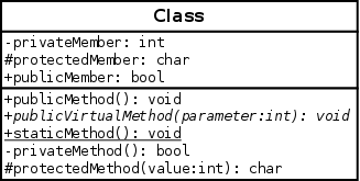
Figure 1: A class
Inheritance
Class inheritance is in terms of UML a relationship of generalization. It represents “is a” relationship on class level. Figure 2 shows how to portray generalization.

Figure 2: Inheritance
Realization
UML has different relationship for interfaces. When you inherit from an interface you implement it, which is in terms of UML a relationship of realization. It’s visual appearance is similar to inheritance, but the line is dashed. Also the interface class should be marked as abstract (have name written in italic). See on Figure 3.

Figure 3: Realization
Association
Another form of relationship in class diagram is association. It’s a object-level relationship (i.e. happens between objects of associated classes). So the whole relationship represents a family of links. There are multiple types of association with stronger policies (composition and aggregation).

Figure 4: Association
Aggregation
Aggregation is a stronger and more specific form of association. It’s “has a” relationship. Graphical representation of aggregation is shown on Figure 5.

Figure 5: Aggregation
Composition
Even stronger form of aggregation is composition. Instead of “has a” it represents “owns a”. It’s suited for relationship when one object can only exist as a part of another. For example if a plane has a wing it’s a composition. What would you do with a wing alone, right? The plane owns it. But when a pond has some ducks in it it’s an aggregation. The ducks will survive without a pond (only probably not that happy). And a pond will still be a pond with or without ducks. Graphical representation of composition is virtually the same as aggregation, only the diamond is filled (see on Figure 6).

Figure 6: Composition
Dependency
Last type of relationship is a dependency. It’s weaker then association and it says, that a class uses another one and therefore is dependant on it. The use of dependency is appropriate for example in cases where an instance of a class is stored as a local variable inside another classes’ method. Or some static methods are used, so the classes are not associated, but one depends on the other.

Figure 7: Dependency
Cheat Sheet
I did all the examples in an open-source diagram editor called Dia. I recommend it by the way. And because it’s such a wonderful editor, here’s a complete cheat sheet (if you’d like to print it).

UML Class Diagram Cheat Sheet
Interface Segregation Principle in Software Design
ISP, not Internet Service Provider, but Interface Segregation Principle is the last of the famous principles of SOLID object-oriented software design. It was introduced by Robert C. Martin in his series of articles in 1996. Intention of this principle is to avoid creation of “fat” interfaces.
A fat (or polluted) interface comes from extending current interface with some functionality that is useful only to a subset of entities that depends on it. This phenomenon leads eventually to creation of dummy methods just to be able to use the interface. And that’s bad. Dummy methods are dangerous and also violate the LSP. The ISP as wrote the author declares that
Clients should not be forced to depend upon interfaces that they do not use.
Each interface should have clearly defined purpose and make reasonable abstraction of a part of the current problem. The best practice (in my opinion) is to use multiple inheritance when implementing the interfaces. This method will separate things that don’t logically belong together on the abstraction level and clean wrong dependencies in our code. But it also allow us to couple them back together in objects, that cover multiple things and work on the same data.
Let me show an example of how it should not look like. This is an interface for a car.
/* Bad example */
class CarOperation
{
    public:
        virtual void steer(int degrees) = 0;
        virtual void pullHandbrake() = 0;
        virtual void accelerate() = 0;

        virtual void shift(int gear) = 0;

        virtual void toggleAirConditioning() = 0;
};
There are a couple common things you can do with a car. Every car usually has a steering wheel, an acceleration pedal and possibly even a handbrake. But what about those cars with automatic transmission? They don’t allow the driver to shift gears, so what should they do with the shift method? The interface enforces it’s implementaion. And again with air conditioning. Some cars don’t have an air conditioner. The way here is to split CarOperationinterface into a couple smaller ones.
class BasicCarOperation
{
    public:
        virtual void steer(int degrees) = 0;
        virtual void pullHandbrake() = 0;
        virtual void accelerate() = 0;
};

class GearboxCarOperation
{
    public:
        virtual void shift(int gear) = 0;
};

class AirConditioningCarOperation
{
    public:
        virtual void toggleAirConditioning() = 0;
};

class AlfaRomeo166 : public BasicCarOperation, GearboxCarOperation, AirConditioningCarOperation
{
    /* Implementation of all the interfaces. */
};

class SkodaFavorit136L : public BasicCarOperation, GearboxCarOperation
{
    /* No air conditioning for old cars. */
};
The clients that will use the concrete cars won’t look at them directly as AlfaRomeo166 or SkodaFavorit136L. They will operate them through the interfaces. If some client function wants to turn on a air-conditioning it will look like this
void beCool(AirConditioningCarOperation* vehicle)
{
    vehicle->toggleAirConditioning();
}
That’s the beauty of interface segregation principle. You get exactly what you need, nothing more and nothing less, which makes the code easier to maintain, reuse and saves you from a cascade of unpredictable errors, when you decide to modify existing code.
Sources
Hello Lua
 Back in the day, when I used to play World of Warcraft (shame on me), I noticed they use something called Lua to let players extend their user interface with various addons and tweaks. It worked very good. There are literally thousands of available addons for World of Warcraft. I quit the game about 2 years ago and I never got to look further into Lua, until now.
As it turns out, Lua is quite popular among game developers as an extension scripting language due to it’s C API. Common practice is to implement the engine and some basic game features in C++ and then script all the content in lua. That way it’s easier to tweak the game, because it’s not hard-coded and compiled. As the official website says:
Lua combines simple procedural syntax with powerful data description constructs based on associative arrays and extensible semantics. Lua is dynamically typed, runs by interpreting bytecode for a register-based virtual machine, and has automatic memory management with incremental garbage collection, making it ideal for configuration, scripting, and rapid prototyping.
Sounds pretty neat. And on top of that, lua is open-source. It’s distributed under the MIT license!
Sources
Building Ogre3D from Sources on Fedora 15
This is a little walk-through the whole build process of Ogre 3D rendering engine. It’s primarily for users of Fedora GNU/Linux distribution or any similar distro that uses rpms and yum. I chose the variant using cmake, so first thing you want to do is install cmake.
$ su -c 'yum install cmake cmake-gui'
After that there are also some prerequisites, that you need to install. For the Cg package you’ll need to enable rpmfusion nonfree repositary by writing
$ su -c 'yum localinstall --nogpgcheck http://download1.rpmfusion.org/free/fedora/rpmfusion-free-release-stable.noarch.rpm http://download1.rpmfusion.org/nonfree/fedora/rpmfusion-nonfree-release-stable.noarch.rpm'
Then install the dependencies using
 $ sudo yum install gcc-c++ libXaw-devel freetype-devel freeimage-devel \
                    zziplib-devel boost-devel ois-devel Cg doxygen \
                    cppunit-devel
Some of them are optional, but I like to install them all, just in case. Since the hard-drive space is no longer an issue, it could save you from having to build it all over again. After that proceed to downloading the latest version of Ogre3d source and unpack it somewhere.
 $ cd ~/Downloads
 $ tar xjf ogre_src_v1-7-3.tar.bz2
This will extract the sources into a new directory. Let’s rename it to source. Then we’ll need another directory where all the binaries will be places. Let’s call it build. After that run cmake.
 $ mv ogre_src_v1-7-3/ source/
 $ mkdir build
 $ cmake-gui
In the gui set both paths to the source and to the build directory and hit Configure button, leave the defaults (Unix Makefiles and Use default native compilers).
")

Check the Advanced and Grouped check-boxes and make sure you have installed everything you might need. If you compile ogre without some features here, you’ll need to do it all over again (I did it 4 times when I compiled Ogre for the first time). You should have installed zzip, zlib, freeimage, freetype, boost, opengl, X11, and ois. If you don’t, I highly recommend to install those libs and hit configure again. When you’re done, hit Generate.
At this point, we’re done with the cmake, you can close the window and get back to your terminal window. Now we proceed to the building process itself. Change to the build/ directory and run make to compile Ogre3D and wait.
 $ cd build
 $ make
There will be percentage coming up as the library builds. It takes (on my machine) a solid half-hour to build, so feel free to go get some coffee. The only thing left is installing the compiled library to your system using the classic
$ su -c 'make install'
Enjoy your Ogre!
Sources
Dependency Inversion Principle
DIP or Dependency Inversion Principle is yet another guideline for the software designers that work in object-oriented environment. It’s the D in SOLID and it has one huge advantage over the other principles: in case it doesn’t work for you, you can always get some tortilla chips to help (they work wonderfully with dip ;-)).
This principle was introduced by Robert C. Martin in his article in 1996. He points out that the usual way of dependency design among software project is to make general high-level modules dependent on the low-level utilities and mechanism that do the hard (and in most cases also not very interesting) work. This way of dependency makes the high level modules very hard to reuse without many modifications (and people often thing “why the hell didn’t I wrote it again”). And this is wrong.
The high-level modules are key part of the application. That’s where the heart of the application actually is. The algorithm that knows how to use the lower-level modules to achieve the desired functionality of our application. And we want to reuse that without having to modify every third line, so what do we do?
Mr. Martin proposes the Dependency Inversion Principle, which says
A. High level modules should not depend upon low level modules. Both should depend upon abstractions.
B. Abstractions should not depend upon details. Details should depend upon abstractions.
It’s a little tough one to understand at first, so let me explain. The principle states, that there should be some additional layer between high and low level modules — the layer of abstractions. The author says, that there should be an interface (or abstraction) defined between those two modules on whom should both depend. That way high level modules don’t work directly with the low level classes. Low level classes implement the interfaces. In case you’d like to take some module out and use it elsewhere, you don’t need to touch anything inside that module. You simply take it out and implement the interfaces upon which the module depends. Isn’t that awesome?
The second part (part B.) makes clear that the abstractions (or interfaces) should not be designed according to the low level modules (the details). That’s something that might come naturally to a lazy coder “yeah, I’ll just duplicate the header file, make all methods pure virtual and I’m good to go”, no. The interfaces have to be implemented on the same level of abstraction as the high level module otherwise they’re more than useless.
Example of Dependency Inversion
That would be the principle in theory. Let’s see some examples from user interfaces. We’ll have a Window class with two buttons.
class Button
{
    public:
        void makeVisible();
};

class Window
{
    Button* okButton;
    Button* cancelButton;

    Window()
    {
        okButton = new Button;
        okButton->makeVisible();

        cancelButton = new Button;
        cancelButton->makeVisible();
    }

};
The problem here is, that if the Button implementation changes, we’ll have to go here and change the constructor as well. We don’t want that, because the Window class were a subject of a lot of tests, it passed and any additional messing around in it might introduce errors into the class. Using the abstraction layer the situation would look like this
class IButton
{
    public:
        static virtual IButton* getInstance() = 0; // factory method
        virtual void show() = 0;
};

class Window
{
    IButton* okButton;
    IButton* cancelButton;

    public:
        Window()
        {
            okButton = IButton::getInstance();
            okButton->show();

            cancelButton = IButton::getInstance();
            cancelButton->show();
        }
};

class Button : public IButton
{
    public:
        void show();
};
Now, as you can see, there’s an interface IButton and both Button and Window depend on this interface. And that’s the dream. You can take the window and the interface place into an another application, implement the interface and you’re good to go! Note the factory method I used to be able to get the correct instance of buttons.
Sources
Design Patterns: Renderer
This post about design patterns will be a little unusual. To this day, I was going through a generally recognized set of design patterns that was introduced by the Gang of Four in Design Patterns: Elements of Reusable Object-Oriented Software. But today I want to introduce to you a useful design bit I came up with, while I was working on my bachelor’s thesis. I call it Renderer.
The problem I had was simple — unbelievable mess in my application’s source code. I was working on a procedural approach to rendering cities. And believe me, a city is kind of big-ass model to draw. There’s awful lot of rendering of different things on different places. And when it comes together it’s a giant blob of instructions. So I needed some way of structuring this rendering code and making it readable and if-I-got-lucky also extensible (don’t judge me, the due date was really haunting me in my sleep at the time). Finally I came up with a tree-like data structure.
What is a Renderer?
Glad you asked! It’s a class that renders stuff. The concept is reeeeeally simple, but it’s very powerful when you need to structure your code properly. The definition of the class is as simple like this
class Renderer
{
    public:
        virtual void render();
};
It’s actually more like interface. Every Renderer must implement this interface. The render() routine renders the content of the current renderer. The beauty of this concept is in the fact, that you can organize your renderers into a tree. The top-level renderer will render the object by delegating rendering of different parts to other renderers. This makes your code nicely structured as well as modular and reusable. Take for instance rendering of a car.
Cars can be visually relatively complex objects and it wouldn’t be nice to have all the rendering code in one class. If you wanted to draw a different car you’d have to write everything again even though that wheels are virtually the same in both models. But with using the renderer pattern, things would look like this
class CarRenderer : public Renderer
{
    CarBodyRenderer *body;
    WheelRenderer *wheels[4];
    WindowRenderer windshield;

    public:
        void render()
        {
            body->render();
            windshield->render();

            for (int i = 0; i < 4; i++)             {                 wheels[i]->render();
            }
        }
};

class CarBodyRenderer : public Renderer
{
    SpoilerRenderer* spoiler;
    HoodRenderer* hood;
    SkeletonRenderer* skeleton;
    DoorRenderer* doors[5];
    public:
         void render();
};
I guess you get the idea. You decompose the object into a set of smaller entities and render them instead. This decomposition can go on virtually forever, in extreme cases you could be able to render a car from pixels using this design pattern and still be able to look at your code and understand it. Anyway, let me know if you find this pattern useful!
